


DOLPHIN® SEMI AUTOMATIC Y – MAZE
CODE : 1201
SEMI – AUTOMATIC Y-MAZE
The SEMI – AUTOMATIC Y-MAZE
has been developed by us for the study of shock-motivated Brightness Discrimination response in rats.
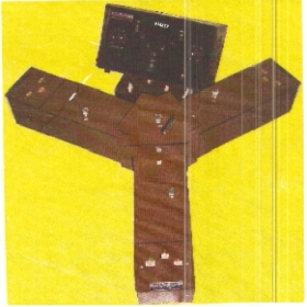
It consists of :-
1. Three sun-mica line chambers arranges in Y-shape, removeably connected to a central chamber.
2. Each arm has a working dimension of approx. 30 x 15 x 15 cms, with chamber light, cue light, and
Grill charge indicator, rat presence indicator removable central dividing door and hinged top.
3. The central portion also contains a wire grill.
4. Separate stimulus and control unit with approx. 5 meter long leads.
5. The control unit has a replica of the Y-Maze with facility of indicator of the condition of each chamber.
6. A per-programmed rotary switch controls the experimental procedure, including cue lights
(Visual stimulus) and shock stimulus
7.Facilitates conduct of an experiment with out disturbing the animal.
8. Operates of 220 V.A.C. only.
INSTRUCTION MANUAL FOR SEMI AUTO MATIC Y- MAZE
The SEMI AUTO-MATIC Y-MAZE has been developed by us for the study of shock hublot replica motivated Brightness Descrimination Response in rats. It consists of :-
1. A central chamber with grid-floor and removeable top.
2. Three identical alleys. Each alley has:-
a) A cue- light, yellow which also illuminates the inside of the alley.
b) Grid- floor charge (shock) indicator, red.
c) Rat presence indicator, Blue (or green)
d) Removable central dividing door, and
e) Hinged top lid.
3. An electronic control and stimulus unit.
4. Four connecting cables with connectors.
A-DESCRIPTION
1. Central Chamber :
i) It has three openings to which the three alleys are connected by pushing them in by about
a centimeter.
ii) A removable top lid.
2. Alleys of Y-Three identical and interchangeable alleys which snugly fit into the openings of the central chamber. Each alleys has:-
i) A long chamber with a removeable dividing door.
ii) A balanced grid floor which is charged electrically and tilts down by the body weight of the
rat entering or remaining in it.
a) The middle one (Yellow or amber) is the CUE LIGHT, it lights up when the alley arm lights up.
b) The red indicator lights up when shock stimulus is applied to the grid floor.
c) The blue (or green) light indicates the presence of a rat in the alley.
v) A Six pin male socket at one end for connecting its cable.
3. A Control Unit Is Provide:-
i) Shock stimulus variable from 0.1 to 1ma.
ii) Pre-programmed control of the experimental procedure by means of a rotary switch.
B-SETTING UP
1. Arrange a table with adequate surface area to accommodate the Y-maze.
2. Place the central chamber in the middle of the table top.
3. Push in the three allays into the openings of the central chamber, to form a Y. All the alleys are interchangeable and un-marked so that any alley may form any arm of Y.
4. i) The connect cable A to one arm, cable B to the next arm at left and cable C to the
remaining arm so that the cables with cables with their alleys are in a clock-wise direction.
ii) The fourth unmarked cable with two pin connector goes to the central chamber.
iii) Care should be exercised while pushing the connectors to their respective receptacles.
The plugs and sockets are polarized and will mate only in one position.
5. i) Keep the electronic stimulus – control unit either on the same or another table. The
Cables are long enough to permit stimulus unit to be kept far away or in another room.
ii) A replica of the Y-maze appears on the front panel of the control unit, showing the positions and conditions of the Y-maze.
6. Connect the cables to their respective sockets marked A, B and C at the back of the control unit. The fourth cable will connect into the unmarked two pin – socket.
The setting up, of the apparatus is now com-
C-OPERATION
1. Keep intensity – ma control at 0.1.
2. Keep the start Box Control at A (lower)
3. Connect the mains cable to 220 / 230V single phase 50 Hz A.C. or any other type of supply.
4. Switch on. The pilot will light up and LED bulbs on the replica o Y-maze will light up along with similar indicators on the alleys.
5. i) As the start Box control is at A (lower), the alley A becomes the start box, in which rat is
Placed to begin the experiment.
6. When the Start box switch is rotated one step clock- wise, all the indicator light of the Y-maze will go off. Only the presence indicator will be on if a rat is present in that alley.
7. Rotating the start Box switch another step clock – wise to B, will change the pattern at 5, making alley B, an start Box and alley C as entry box.
8. The Start-Box Control is always rotated clock – wise. It will automatically change the direction after three runs. The following procedural sequence are obtained:
START-BOX ALLEY AS ALLEY AS TERMINAL ALLEY
BOX START BOX BOX (CUE LIGHT) WITH
SWITCH ON SHOCK
POSITION ON
A (lower) A B AC
0 OFF
B B C BA
0 OFF
C C A CB
0 OFF
A (UPPER) A C AB
0 OFF
C C B CA
0 OFF
B B A BC
A (lower)
The above sequence is repeated.
It will be seen that the rat is first forced to move in a clock wise direction and then anti clock – wise .
9. The shock intensity may be varied by the INTENSITY. Ma control to suit the rat.
10. When the rat reaches into the desired alley the Start – Box switch should be rotated one – step clock wise to switch off Cue – Lights and Shock Indicator Lamps. Only the rat presence indicator will remain alight.
D – PROCEDURE
1. The subject (rat) is placed into the nonilluminated Y-maze for 10 minutes to adopt to the new environment. During a non-stop training session the subject has to learn a shock motivated brightness discrimination.
2. The Y-maze is so programmed that the alley on the left of the left of the start box (where the rat is placed) is illuminated (Cue-Light on). Shock current flows via the floor grid to all parts o the
Y-maze except the illuminated alley (terminal box) so that the rat should finally enter the illuminated alley to escape the foot shock.
3. When the rat enters the illuminated alley (terminal box) the shock current should be switched off for about 25 seconds.
4. A run is considered to be positive when the animal immediately runs into the illuminated alley and the previous escape (run), if any, into the non-illuminated alley is designed as negative run.
5. The light in the terminal box is switched off for about 25 seconds. This is followed by a stochastic time interval before the next foot shock is given.
TRIAL NO. INTER-TRIAL
INTERVAL
6. The terminal box now become the start box. The average times interval between two successive foot shocks is 60 seconds.
7. The direction of alley allumination is automatically changed after every three runs to avoid position discrimination.
8. A response is considered to be correct when the rat runs immediately into the terminal box in the last run prior to and in the first run after the change in the direction of alley illumination
.
E – GENERAL
1. Electric shock to grid floor is OFF only when the Start – Box control is at any one of its off position. Only when the electric shock is off, the action of grid floor may be checked by pressing it down light up when the grid – floor is pressed down.
F - CAUTION
1. Grid – Floor carry replicas relojes electrical current which gives a very nasty shock if touched.
2. It is better that the apparatus is completely disconnected from mains, before any metallic part inside the alley is touched.
Cheap fake rolex watches uk online store - All perfect replica Rolex watches are all available. kopior klockor
Copyright© 2019 DOLPHIN PHARMACY INSTRUMENTS PVT. LTD. . All Right Reserved
Design By 